Shakespeare wrote in the play Hamlet: “When sorrows come, they come not as single spies but in battalions.” And while the current trio of bikes was more sorrowful for the owners, they meant a lot of troubleshooting and problem-solving for my little workspace this month.
First...
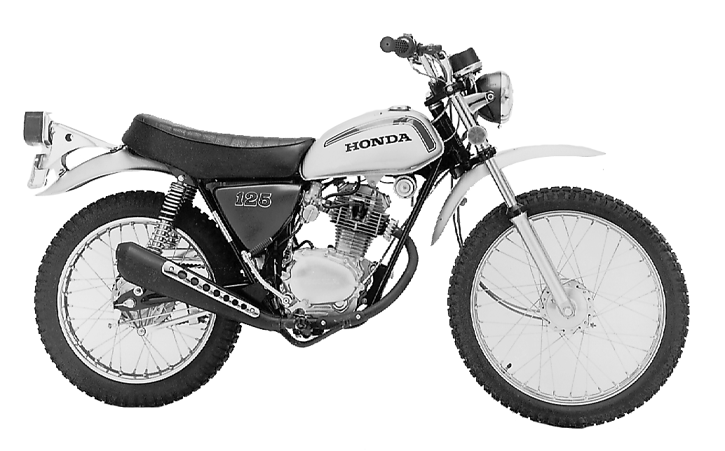
After the SL125 bike revival a few weeks ago, the owner brought back another SL125 engine that was caked with baked-on mud and grease. He thought that it needed a “top end” work and brought the engine over with both side covers removed, as he was going to clean/paint them.
Having built a successful road racer out of a similar CB125S1 engine, the engine was no stranger to me; although I had to brush off a few dormant brain cells to remember a couple of the steps.
The cylinder head had some carbon buildup and while the intake valve seat and valve faces contact looked good, the exhaust valve seat was dull and pitted. I have some old Honda valve seat cutters that fit the seat and stem size, but they generally leave a rough surface that needs a lot of lapping to complete the seal. Despite a round of power washing and paint thinner cleaning, a lot of gunk remained stuck in the porous surfaces. The owner didn’t want to pay for vapor blasting the top end as the bottom end was still stained and dirty and we weren’t going into the bottom end.
The cylinder came off and there were several rings of stains where moisture had gathered at times, but after my machinist hit the cylinder with his Sunnen hone, it looked like it would be useable. The piston ring gaps were close to new specs, so it hadn’t been run in a lot since it was apart before.
The case bolts had all been changed to large Phillips head screws previously. That could mean that just the screws were replaced or that the bottom end was opened up for service work. Its previous history is unknown. The owner supplied gaskets, seals, an Allen bolt screw kit, and instructions to redo the top end as needed.
Whatever was used to glue the gaskets on the engine last time was very time-consuming to remove. After replacing the one exhaust valve stem seal and reassembling the head, the top end started to come back together again with new gaskets, but reusing the piston, rings, and STD bore cylinder. There were some metal chips in the remaining oil that dripped out of the side cases and inside the centrifugal oil filter on the end of the crankshaft. I could see some wear inside the cam chain tunnel where the chain had been left un-tensioned and it carved a bit of aluminum out of the inside of the cylinder block. The bottom filter screen was checked and cleaned, so all that was waiting for was the side covers.
The carburetor attached was another Taiwan Chinese copy, with no marked jet sizes. I cleaned out the blocked pilot jet and the rest of the float bowl components, the readjusted the float level to 25mm which was initially set about 22mm for some reason.
The carb was reinstalled with the sandwich of gaskets, o-rings for the intake insulator, manifold extension and carb flange.
One down and two to go….
In the meantime, while the SL125 engine was on the bench, my friend Don brought over a CT70 that his buddy had bought from a guy who has a bit of an assembly line in Hemet, CA, rebuilding these little Mini-Trail 50-70s. Visually, it looked great, but when it was started up, some oil came shooting out the side of the cylinder from a hole where the cam chain guide roller pin is supposed to be located. He shut it down right away and brought it over for me to look at and repair. Thinking it was going to be a 1-hour fix, I was not prepared to see that the cylinder assembly was alloy and marked Takagawa on the upper edge. Factory cylinders are cast iron, so I suspected that it was some kind of 88cc big bore kit installed on a stock motor.
I had hoped to be able to remove the top end, install a Heli-Coil in the 8mm hole and button it back up again, but as soon as the cylinder was removed, I saw deep seizure grooves in the top of the piston skirt and there were some matching grooves in the cylinder. Baked-on oil deposits on the piston crown indicated that it had been burning oil for quite some time. The cylinder walls were paper thin and the piston was 52mm, I think.
Keeping it on the cheap, eBay sellers offer tons of Chinese aftermarket parts for little 50-70cc Honda for dirt cheap. A whole top-end kit is $100 with free shipping! Sounded like the best plan, however, as my luck would have it the replacement parts are modeled after the CRF70 apparently, as the combustion chamber is smaller, as are the valves but the big issue was the piston crown height. With the cylinder down over the piston, at TDC there was about a 20mm gap from the edge of the piston crown to the top edge of the cylinder. Generally, the head gasket is the main provider of the “squish band” needed to help stir up the mixture and that is in the .040” range. I was looking at a .080” space in addition to the gasket thickness.
Going on the FB forums for Z50s, I got a conversation going with a Mini-Trail guru, Josh Eule, at JE Vintage Honda Minis LLC https://www.vintagehondaminis.com/ and he said the solution is to get an original style piston/rings and use the original cylinder head. The only other concern is that the camshaft has a mark on the end that leads me to think that it is a Takagawa performance cam, which may not play nice with an otherwise stock CT70 engine.
I did dismantle the cylinder head, clean the valves and lap the seats in so it will have the best compression possible when it is all done in the end.
There’s
never a dull moment in MrHonda’s Casa del Plata workshop space...
And finally….
A bike that I worked on a few years ago for a young high schooler, had disassembled the engine and asked me to rebuild it, while he was finishing up rebuilding the chassis. He, apparently, has access to a vapor blaster and was bringing in all the parts, ready to go. After comparing my local guy John, who does amazing vapor blasting work, he agreed that the parts needed another run-through to get them looking really great.
Problems arose when John sent back a photo of the lower engine case with a huge chunk missing from the bottom where a chain had gone through. I tracked down a good replacement from eBay sellers and had that shipped in. The upper case had its own problems with a broken off case bolt and a broken off kickstarter bolt hole boss towards the front of the engine. I had Rob North do the bolt extraction and welded up the broken boss. I didn’t have a kickstarter cover to help locate the hole for drilling and tapping, so that will wait for later.
The cylinder head had mashed fins on one side, so an appeal to the 250-305 Forums on Facebook yielded a reply from a local San Diego enthusiast who had a bare head with one broken fin at the top corner, which would normally be somewhat easy to repair. Again, Rob North lended his talents to the job and built up a good section of fin material to the head. John, not only has the vapor blaster, but has a small lathe and mill in his shop and was able to machine the fin down to near perfect for this engine.
All the parts were cleaned and all holes re-tapped to get the media out of the deep recesses of the screw holes.
The pistons and rings looked to be fairly unused. I had my machinist hone the bores and they came out looking great. The ring end gaps were in specs on the .25 oversized pistons that had been installed long ago, so that was all reused. The cylinder head got a fresh set of OEM valves and a valve job at the machine shop.
There was a lot of running around San Diego, gathering parts and getting specialty services performed in order to get the engine parts arranged for installation and assembly.
I had problems getting the rotor off the end of the crankshaft, due to someone attempting to remove it with a 3-jaw puller and damaging the first few threads of the rotor where the removal tool inserts. I forced the 16x1.5 Honda tool into the first few threads and kept hitting the handles with a hammer to continue rotating the tool into the threads. At some point, the rotor popped off the end of the crankshaft. I had to put it in a vise with the tool handle down and used a big pair of Vise-grips to spin the rotor back off of the threads. I ordered a 16x1.5 tap for $10 and will clean up the threads from the inside out to save the rotor from being scrap.
I got an endless cam chain from Tim McDowell’s website and looped it over the crankshaft before dropping it into the crankcases. In went the transmission shafts after the shift drum and forks were reinstalled. Checking the gear dog engagement was surprisingly good, so I saved my few offset cotters for the next go-round with an upcoming engine project. In went a new low gear bushing and kickstarter pawl and plunger/spring assembly, along with new seals. A coating of MotoSeal on the bottom case half was applied and the cases were reunited again.
Flipping the cases over, the center cam chain guide roller was installed, now available from CMSNL.COM. The pistons were installed with new clips on the pins and rings were checked for end gaps. With the nearly stock bores and chamfers at the bottom, the cylinders slipped right down on the pistons with little effort. The OEM head gasket was installed with a coat of MotoSeal around the o-ring holes to lessen the possibility of oil migrating through the gasket.
The tricky part of installing the endless chain is that you have to install the inner ball bearings into the head and leave the cams out until you slip the chain over the cam sprocket in the narrow channel. Making sure that the right side piston is on the T mark, you work the cam chain around until the flat on the cam sprocket is even with the head and the 0 punch mark is at the top. I put a couple of short sockets on the studs and add a few nuts to help cinch down the whole cylinder head and cylinder stack while the cam chain is held steady and camshafts are inserted into the master splines very carefully. It is a juggling act but with persistence, the cams finally insert into the sprocket. You have to tap in the right side point cam end slowly until it engages with the slotted plate in the cam sprocket center. Once the cams are inserted you have to push the bearings inwards to clear the edges of the cylinder head surface so the end covers can be installed to the correct depth.
Once the cams are located correctly in the head, you have to cinch down the locking bolt on the left side of the engine and then tighten down the locking nut on the right side cams. Looking at the top of the head, the left and right sides are reversed from what is normally called left and right when you are riding the bike. With cams secured, the valves can be adjusted, covers installed, and then the top gaskets, baffle plate, and top cylinder head cover secured with new sealing washers and nuts. Torque the nuts down to about 16 ft. lbs and you are just about done with the top end.
All the clutch and primary parts can be installed before or after the top end is done. A careful cleaning of the oil filter adding the missing o-ring ensures clean oil getting to the crankshaft and top end bearings. I had a better primary chain than the one that came out. The original one was walking off the clutch basket and rubbing notches against the shift shaft! You have to check EVERYTHING when you reassemble a 50+ year old vintage Honda engine.
All in a day’s/week’s work for MrHonda
6/23